Achintya.

Project 03 · Designer & Builder

Tennis Ball Feeder

A self-built training machine exploring mechanical design, electronics, performance, and affordability — designed so players can train solo for hours without a feeding partner.

01Problem statement

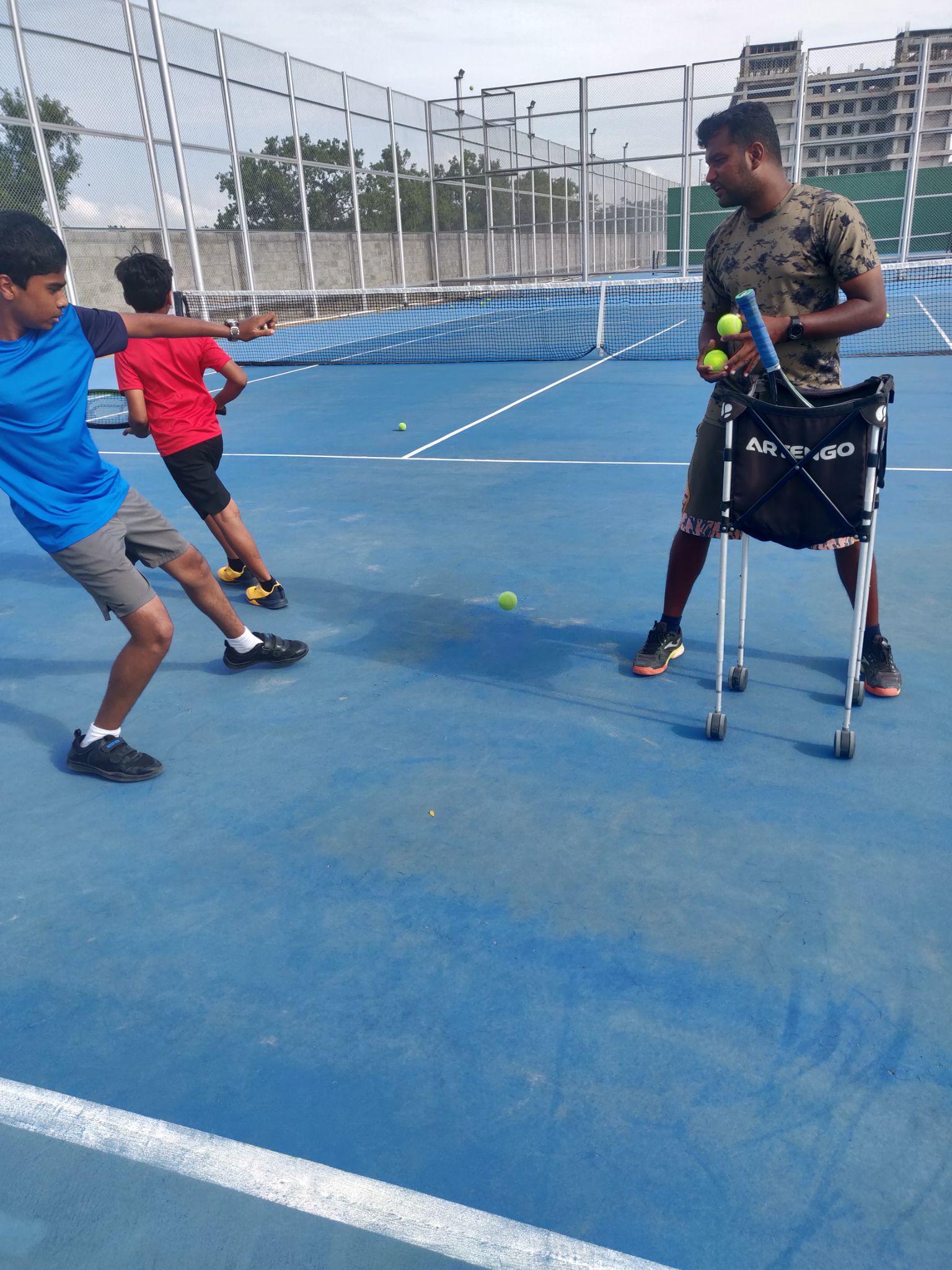
Tennis is about grooving strokes through repetition, and that requires someone to feed balls incessantly. Coaches find it difficult to feed balls while simultaneously watching a student's technique, and varying the feeding pattern frequently is cumbersome. This hampers training effectiveness and is economically inefficient for players.
02The consequences

Players cannot self-train for long hours without a partner or coach, so they spend more on coaching — which is expensive and less effective, since the coach is feeding balls rather than correcting strokes. Training schedules depend on the availability of others, which hinders development.

03Background and motivation

As a competitive player, Achintya experienced this limitation directly. The need: a machine that automates ball feeding with customisable speed, direction and angle, so players at all skill levels can train solo for hours.

04Target users

Coaches running group sessions, advanced players grooving specific strokes, and beginner and intermediate players who need consistent, repeatable feeds — on club courts, home courts and anywhere a commercial machine is unaffordable.

05User research

Separate questionnaires were written for coaches, advanced players, and beginner/intermediate players. The needs that emerged: variable speed and direction to simulate different deliveries, enough ball capacity for long drills, portability between courts, and a price far below commercial machines.

06Market analysis

Existing commercial ball machines were compared for features, price and limitations. They work, but their cost puts solo training out of reach for many players — the gap this project set out to close.

07Research — battery

A battery analysis compared options including lithium-polymer cells against requirements of cost, capacity, weight and safety, to power two drive motors and two servos through long training sessions.

08Research — ball volume and feed rate

A ball-volume analysis looked at high-intensity drills, where a feed rate of one ball every 2–3 seconds is needed. That rate, multiplied across a session, set the hopper capacity target of 200 balls.

09Research — direction and angle

A lateral-direction analysis set the aiming range: a minimum of 90° to a minimum of 30° between extremes, giving approximately ±60° of directional coverage. Launch-angle adjustability was specified separately so the machine can simulate different delivery styles — flat drives, topspin and slice.

10Material analysis

Candidate materials for the body and wheels were compared in a material scorecard against the qualities the product demanded: strength, weight, machinability, cost and durability outdoors.

11Final specification

The research was distilled into a final specification covering power (40 W), capacity, feed rate, direction and angle ranges, portability, wireless control and cost — the yardstick for ideation and later evaluation.

12Ideation

Five ideation concepts were sketched and dimensioned, exploring different layouts for the hopper, wheel assembly, frame and controls.

13Evaluation

The five concepts were evaluated against the specification, and Design 1 was selected as the final product direction.

14Mechanism analysis — height and angle

Height-adjustment options, including an electric linear actuator, were analysed for range, cost, complexity and user convenience.

15Mechanism analysis — direction

Direction-adjustment options, including a Whitworth quick-return mechanism, were compared. Servos were the final choice: a higher range, cheap, and very convenient for the user. Two 20 kg servos control direction and launch angle.

16Motor power calculation

The drive was sized by calculation: 80 balls weigh about 47 N; at a common 45° launch angle the force on each motor is about 33 N, giving a moment of roughly 4 Nm on each 12 cm throwing wheel. At 12,000 rpm the wheel rim speed corresponds to a theoretical maximum ball velocity of about 151 km/h, with the kinetic energy supplied split between the two wheels.

17Technical implementation

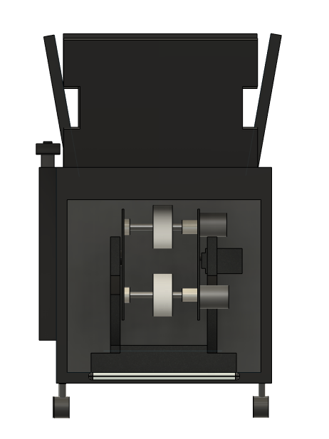
Control is by an Arduino Uno with a wireless remote. Two counter-rotating wheels driven by 775 motors launch the ball; the 200-ball hopper sits above the wheel assembly; final weight is 14.3 kg on a wheeled frame.

18Manufacturing

The frame, mounts and wheel assembly were manufactured using the school's workshop processes, with a full cost breakdown of materials and parts bringing the reported build cost to ₹14,400.

Detailed manufacturing process and cost table to be added from the report.

19Field testing

The machine was field-tested on court with a coach. Reported performance: a maximum speed of 83 mph and directional aiming of approximately ±60 degrees.

20Results and limitations

Reported challenges include battery life, ball jamming, and noise — all documented as areas for further improvement.

21Personal learning

Working through the full design cycle — identifying the problem by talking to players and coaches, writing a specification from research, exploring rough sketches before committing to CAD, and analysing each mechanism on its own merits — taught me that good design is mostly disciplined elimination. The evaluation stage, not the ideation stage, is where the product is really decided.

22Connection to economics and applied mathematics

A commercial ball machine costs many times the ₹14,400 build cost of this one. What does that price gap do to who gets to train? The project is a small study in how the cost of capital equipment shapes access to skill development — and the motor sizing, wheel-speed and launch-angle calculations are applied mechanics throughout.

Photographs & drawings

The problem: a coach feeding balls by hand while trying to watch technique.
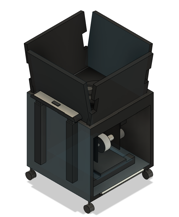
Final design, isometric view: hopper above, throwing wheels and drive below.
Final design, top view: the two counter-rotating throwing wheels.
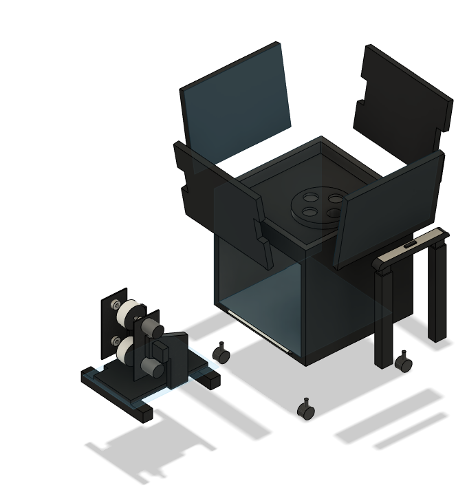
Exploded view: wheel assembly, hopper, frame and castors.